Time To Panic
The controller board now has a place to live. It does not however do anything useful yet. That will be attended to now.
Running Late
Although I feel I was definitely on top things with this project and didn’t procrastinate, I did end up running late. As a result I was payed a visit by the Panic Monster1. About a week from the project deadline two things went wrong at the same time.
First, my 3D printer broke down while I still had to print all the bits needed to attach the lamps a rope. The bracket that holds the bed level sensor broke in half. It’s a printed bracket that’s part of an extruder upgrade. That meant I had to 3D print a new one to get my 3D printer to print again. I daresay you understand the difficulty here. I managed to solve this chicken-and-egg problem with a liberal amount of epoxy glue in the end.
Second, the LED receivers stopped listening to the controller.
Are You Even Listening?
The second problem was more complicated because I had just locked all the receiver boards up in their enclosures. They were never designed to be re-opened. The receiver boards don’t have bootloaders either because there was no memory to spare (or time to code it). Alas, reprogramming them was out of the question.
All the boards were tested before I installed them and they all worked fine at the time. The test setup ran the exact same protocol and sent the same frame addressing all 25 nodes on the bus. So what went wrong? The problem, it transpired, lay in the microcontroller sending the data to the LEDs. I tested the whole assembly with the beefy STM32F407 on my Discovery board. That’s a powerful Arm Cortext M4 MCU whereas the actual controller board runs a meager M0 at a much lower clock rate.
Let’s do a quick recap of the communication protocol to clarify things: the UARTs on the receiving ends are synchronized with the controller by means of a burst signal. After synchronization the data is sent in 9-bit words at 250 kBaud. The burst signal consists of a series of pulses that are 64us in length and have a duty cycle of 50% (or: equally spaced edges at 32us intervals). Those with attention to detail may have noticed that such a signal can’t be generated with a UART that’s configured to send 9-bit words. To pull off the burst trick, I used a general purpose timer to toggle the MCU pin connected to the RS-422 transmitter. The STM32F407 is fast enough to do this and produce a pulse train with accurate timing. The STM32F042 on the other hand is much slower and can’t make the burst signal happen accurately. And that’s a problem.
Luckily there is a solution. The GPIO method may be too slow, but the UART isn’t. But didn’t I just say that wasn’t possible? I did. A UART with 9 data bits sends 11 bits in each packet, so it can’t mimic a pulse with a 50:50 duty ratio. Not in a single pulse, anyway. But it can generate a pulse train with an average duty cycle of 50% by alternatively putting 6 or 5 successive high or low bits on the bus. Because the receivers synchronize on an average time between pulses (or rather between their edges), they can perfectly work with an asymmetric burst signal. Of course it’s still not possible to generate this signal at 250 kBaud because that would be too fast to get to a 64 us pulse width. But it can be done by temporarily reducing the baud rate (to 171875 Baud to be precise). Strictly speaking this is a deviation from my own protocol, but sometimes you have to bend the rules to get things done.
(Back To) Basic
It took a few days to analyze and fix this issue. Meanwhile the deadline crept ever nearer and my firmware could still only send out a test frame that wasn’t too pleasing to the eye. What’s more, I had basically no experience in coding STM32 controllers and there was no time to learn the specifics of these chips in the half-a-week that remained.
That meant the firmware had to be simple. Very simple. I am generally of the opinion that microcontrollers should either run a real time operating system (though admittedly I never took that route myself) or run interrupt-driven code. I’m not a fan of firmware that continuously polls its inputs and relies on delay() calls to do the timing. But given the situation I had to set my beliefs aside for the time being.
Staying In The Loop
And that meant a continuous loop and polling input pins (or ‘ugly firmware’ as I call it; no offense to anyone coding this way).
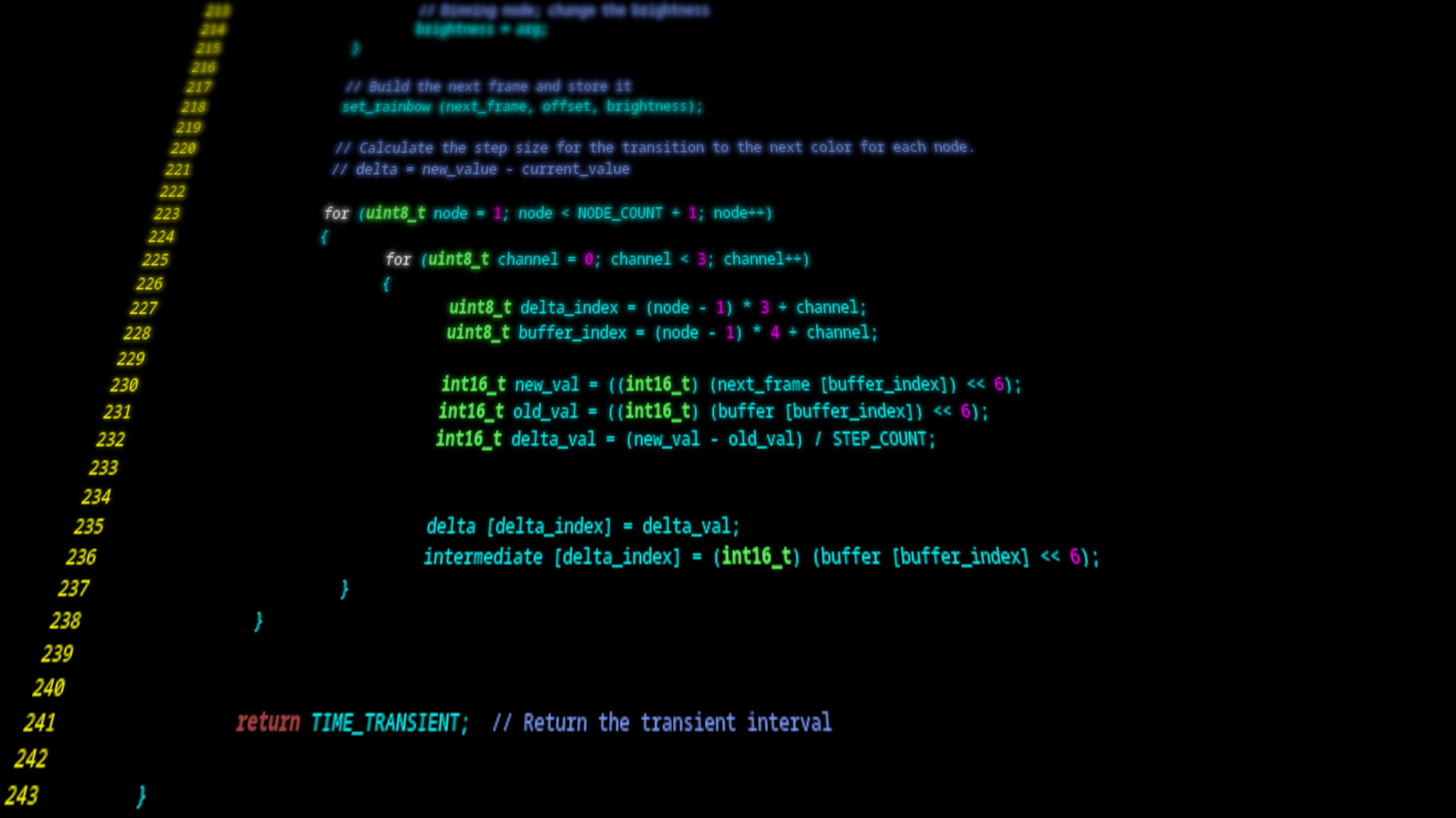
All the program does is generate a rainbow pattern that slowly shifts its position. It updates every two seconds and the colors fade into one another smoothly. The buttons are used to set the brightness for both the white and the colored LEDs. If all the LEDs are turned off the system enters a quasi sleep state, meaning that the power supply to the LED nodes is being disabled but the microcontroller remains active still.
In the end this got me where I wanted to be: a finalized piece of hardware that behaved well enough to be shown to the public. As always you can get the code from my Gitlab repository.
In the next post I will be reflecting on how this project went from a hardware perspective. Proper firmware will remain on my to do list for now.